Her navigators relied on celestial navigation: measuring the altitude of known stars with a sextant and timing the observation against a marine chronometer, then cross-referencing the Nautical Almanac (first published in 1767; produced by HM Nautical Almanac Office since 1832) to fix their position — the sextant giving latitude, the chronometer giving longitude. The 57 “selected navigational stars” — plus Polaris — were the GPS of their age.
The ship’s primary route from 1852–1875 took her from Liverpool, south past the Cape Verde islands, around the Cape of Good Hope, and across the Indian Ocean to Melbourne — approximately 60 days at sea. The return followed the “clipper route” east through the Roaring Forties, rounding Cape Horn. As the ship crossed from the northern to southern hemisphere, entirely different constellations rose above the horizon:
| Route Segment | Key Navigation Constellations | Navigator’s Use |
|---|---|---|
| North Atlantic Liverpool → Cape Verde |
Ursa Minor (Polaris), Ursa Major, Cassiopeia, Orion, Auriga, Taurus | Polaris gives immediate latitude; Orion’s belt rises due east for heading reference |
| Equatorial crossing Cape Verde → Cape of Good Hope |
Orion, Canis Major (Sirius), Leo, Gemini, Cygnus | Sirius — brightest star in the sky — used for precise altitude shots at twilight |
| Southern Ocean Cape Town → Melbourne |
Crux (Southern Cross), Centaurus, Carina (Canopus), Vela, Pavo, Eridanus | Southern Cross locates the south celestial pole; Canopus is the second-brightest star |
| Return via Cape Horn Melbourne → Liverpool |
Scorpius, Sagittarius, Aquila, Pegasus, Lyra | Summer/autumn constellations seen during the eastward return through southern latitudes |
The dry dock allows a circular walk around the ship, entering mid-ship on the port side. This creates a natural narrative loop: visitors begin at the equator (mid-voyage), walk forward along one side seeing the northern departure sky, round the bow, and return along the opposite side through the southern hemisphere constellations — arriving back where they started having completed the full voyage in stars overhead.
The installation uses two types of PMMA fibre optic, each suited to a different role:
Standard end-glow fibre optic transmits light internally and emits it only at the far end. Side-glow (side-emitting) fibre is different: micro-scattering particles are deliberately distributed throughout the PMMA (acrylic) core during manufacture, causing light to leak out radially along the fibre’s entire length. The result is a continuously glowing line.
An LED is butt-coupled to one (or both) cut ends of the fibre. Light enters the core and progressively scatters out along the length. Brightness is highest near the LED and tapers with distance — the rate of taper depends on the fibre’s attenuation (typically 0.2–0.5 dB/m for PMMA). Dual-end illumination (an LED at each end) evens out the brightness profile and is our default strategy for runs over ~1.5m.
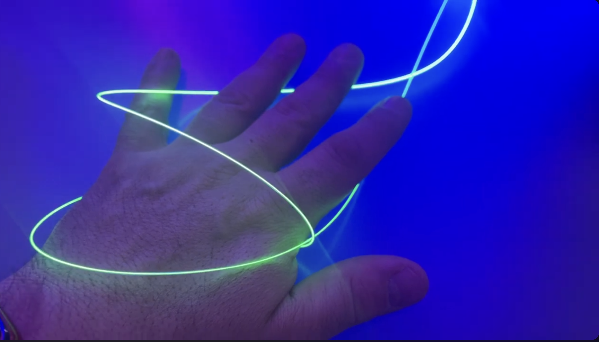
1.5mm PMMA side-glow fibre (available up to 5mm; exact gauge TBC during prototyping). Shown here lit with a green LED; the same fibre can be lit any colour, and we would likely choose blue for the installation.
PMMA (polymethyl methacrylate) is the standard material for large-core decorative fibre optic. It is lightweight, flexible, easy to cut and polish, and transmits visible light efficiently. Our baseline diameter is 1.5mm — thin enough to be near-invisible when unlit, yet large enough to thread through crystal holes and accept useful amounts of light from a small LED. Thicker fibre (3mm) captures ~4× more light and may be used for long flagship runs; this will be determined during prototyping.
| Property | 1.5mm PMMA Side-Glow | 3mm PMMA Side-Glow |
|---|---|---|
| Core material | PMMA (acrylic), refractive index 1.49 | |
| Cladding | Fluorinated polymer, thin clear jacket | |
| Numerical aperture (NA) | ~0.50 (acceptance half-angle ~30°) | |
| Attenuation (side-glow) | ~0.2–0.5 dB/m (varies by manufacturer) | |
| Peak transmission | ~520nm (green); good across 400–700nm visible range | |
| Minimum bend radius | ~40mm | ~100mm |
| Tensile force (side-glow) | ~3–4kg (lower than end-glow due to scattering particles in core) | ~12kg |
| Weight | ~2.0 g/m | ~9.0 g/m |
| UV resistance | Moderate — PMMA yellows slowly under prolonged UV; adequate for covered dry dock | |
| Operating temperature | −40°C to +70°C | |
PMMA fibre cuts cleanly with sharp flush cutters or a dedicated fibre cutter — no specialist cleaving tool is needed. For maximum LED coupling efficiency, the cut end is lightly polished with 400–600 grit wet sandpaper, then seated in a metal ferrule (brass or stainless, 1.5mm or 3mm bore) which aligns it to the LED die. UV-cure optical adhesive bonds the fibre into the ferrule and provides a moisture seal.
End-glow fibre is used for all engine-to-crystal runs. Because end-glow fibre emits zero light along its length, no masking is required — the fibre is invisible in the dark along its entire routing path, with the cut end delivering light directly into the crystal sandwich.
Side-glow fibre is used only for the short constellation edge segments between adjacent crystals — these glow along their full length by design, forming the visible lines of the constellation pattern.
The primary fibre type in the installation is end-glow (end-emitting) PMMA fibre. Unlike side-glow fibre, end-glow fibre has no scattering particles in its core — light travels through the fibre with zero side emission and exits only at the far cut end. This makes it ideal for the engine-to-crystal runs: the fibre is invisible in the dark along its entire routing path, with all light delivered to the crystal.

End-glow PMMA fibre bundle lit from one end — light exits only at the cut tips as bright points, with zero emission along the fibre lengths. Each fibre delivers light from the LED engine to a single star crystal.
Each of the 150 star crystals receives its own dedicated 1.5mm end-glow fibre, routed from the constellation’s twinkle engine along the beam to the mount point, then dropping down to the crystal. The cut fibre end is epoxied into the crystal sandwich, delivering light directly into the crystal body. The same fibre also serves as the structural suspension line — tensioned by a TECNI® TG1.5 gripper at the mount point, it holds the crystal in position.
We use 1.5mm bare (unsheathed) PMMA end-glow fibre (Mitsubishi ESKA CK-60 or equivalent) — the same core material and diameter as the side-glow fibre, making both types interchangeable in the gripper and crystal assemblies. The 1.5mm diameter matches the TG1.5 gripper’s cable bore exactly.
| Property | 1.5mm PMMA End-Glow |
|---|---|
| Core material | PMMA (acrylic), refractive index 1.49 |
| Cladding | Fluorinated polymer, thin clear jacket |
| Numerical aperture (NA) | ~0.50 (acceptance half-angle ~30°) |
| Attenuation | ~0.2–0.35 dB/m at 650nm (lower than side-glow — no scattering losses) |
| Transmission over 5m | ~67–79% of input light reaches the crystal end |
| Peak transmission | ~520nm (green); good across 400–700nm visible range |
| Minimum bend radius | 40mm (per ESKA CK-60 datasheet) |
| Tensile force (5% elongation) | 145N (~14.8kg) — per ESKA CK-60 datasheet. Crystals weigh 30–80g, giving a safety factor of ~180:1 to 490:1 |
| Weight | 2.0 g/m |
| UV resistance | Moderate — adequate for covered dry dock |
| Operating temperature | −55°C to +70°C |
At the crystal end: the fibre is cut flush, lightly polished, and epoxied into the crystal sandwich. The polished cut end is where all light exits — a clean, flat cut maximises the bright point inside the crystal.
At the engine end: all fibres from one constellation are bundled together and inserted into a concentrating ferrule (turned brass, ~8mm bore) that seats in the engine’s 20mm port. The fibres are polished flush with the ferrule face and bonded with UV-cure optical adhesive.
Each star is represented by a crystal — glass, acrylic, quartz, or possibly other semi-precious stones — through which the fibre is threaded. The exact crystal material will be determined during prototyping: acrylic offers matched refractive index with the PMMA fibre for smooth optical coupling, while glass and quartz offer stronger refraction and prismatic effects. Crystal sizes are proportional to the star’s actual apparent magnitude (brightness), and crystal colours match the star’s real colour based on its B-V colour index — blue-white for hot O/B-type stars (like Rigel), amber/orange for cool K/M-type stars (like Betelgeuse).
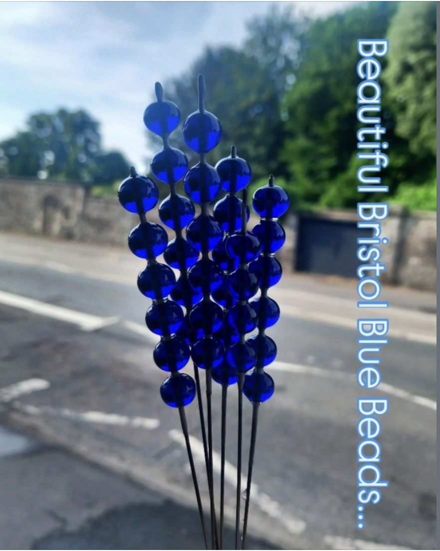
Bristol Blue glass crystals — this vivid cobalt blue could represent blue-white stars such as Rigel, Vega, and Acrux.
Every crystal has its own dedicated end-glow fibre with the polished fibre end terminating inside the crystal, delivering light directly into the crystal body. The fibre is bonded into the crystal with UV-cure optical epoxy, which locks the crystal in position and improves light coupling between the fibre and the crystal.
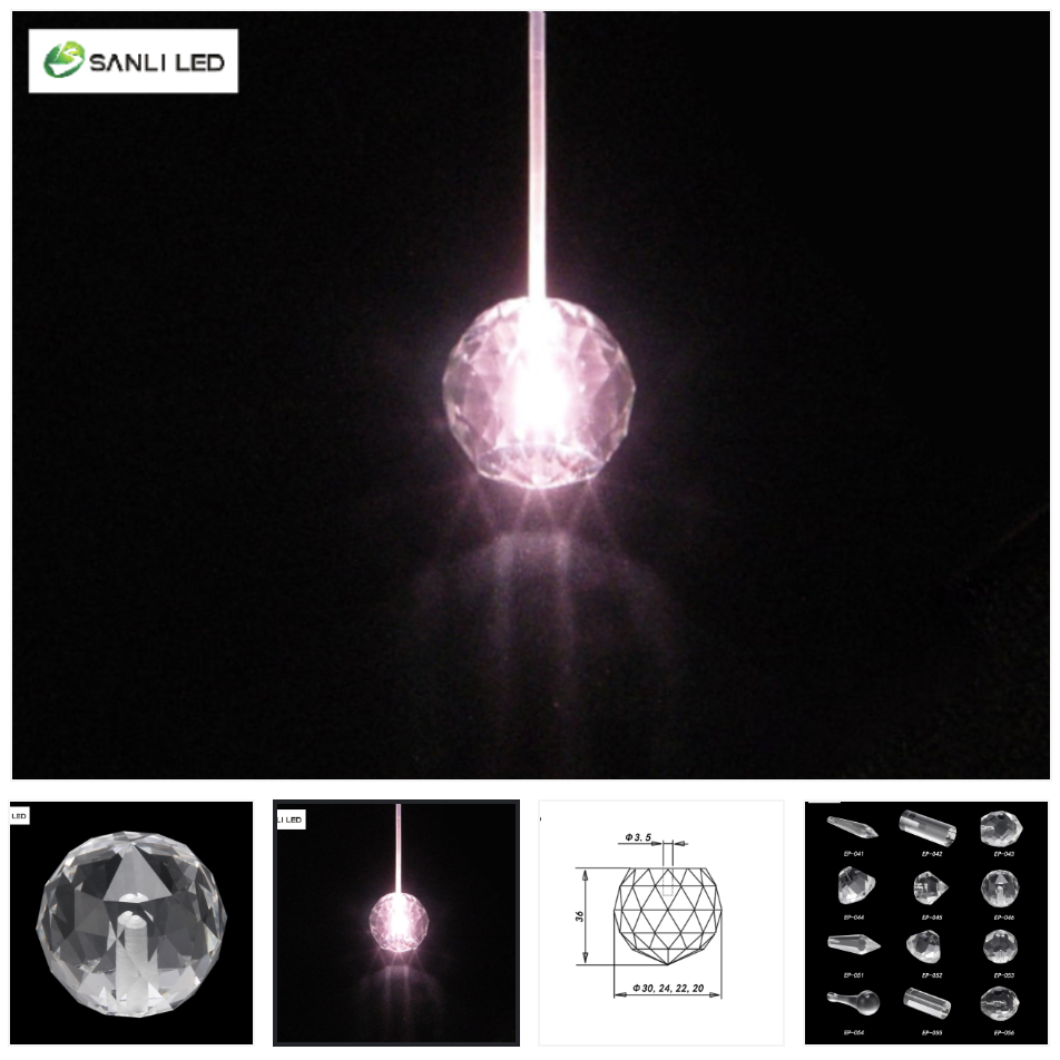
Fibre optic chandelier crystals are an established product category — faceted crystals with pre-drilled apertures designed specifically for optical fibre. These are available off the shelf in a range of sizes and can be used directly as star crystals without custom drilling.
Fibre optic chandelier crystals — an established off-the-shelf component. Right: EP-046 faceted glass fitting (36mm × 30mm, 30g, 3.5mm aperture, accepts fibre up to 3mm diameter).
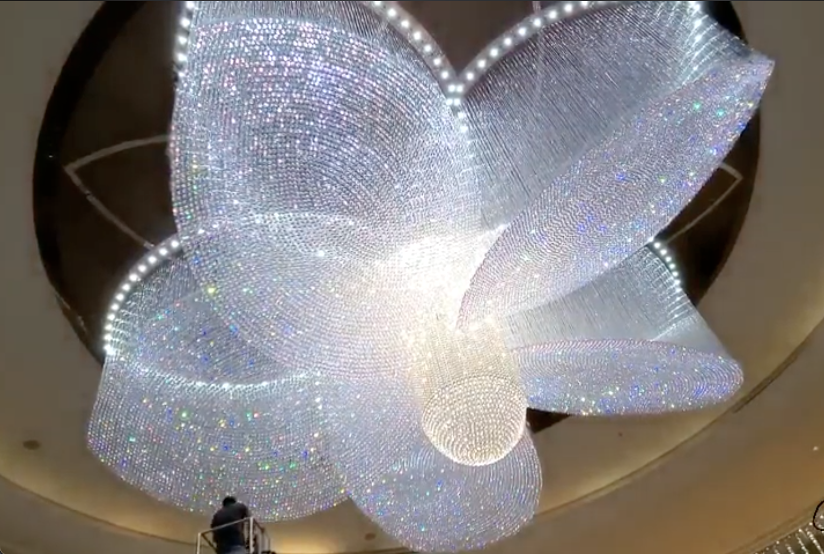
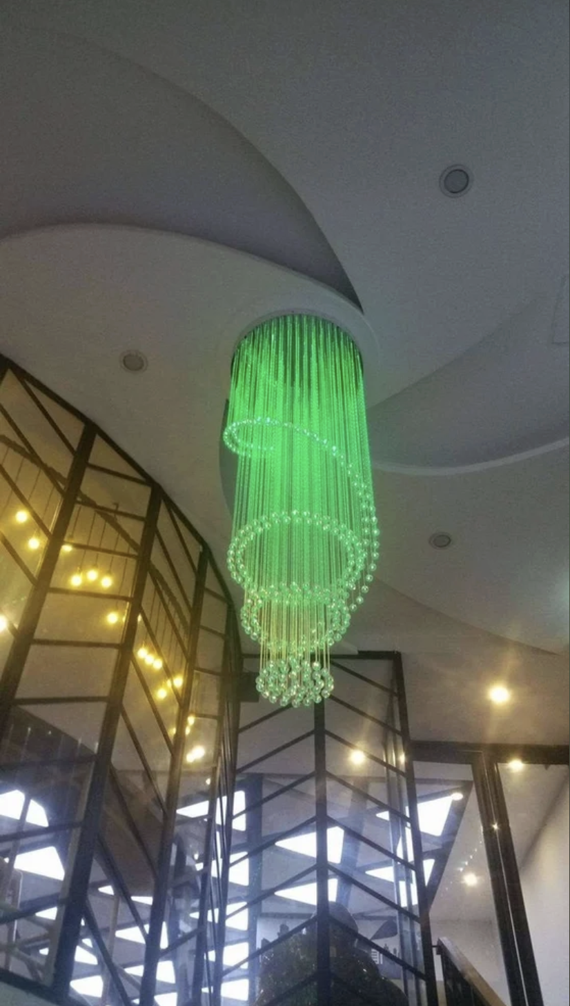
Large-scale fibre optic chandelier — a single light-colour engine feeds thousands of fibres, each terminating in a different-coloured crystal. The crystals hang directly from the fibres, demonstrating the method at architectural scale. Person on ladder (bottom left) gives a sense of the installation’s size.
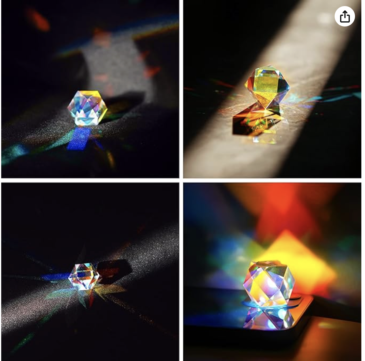
Example crystal reference — faceted crystal prisms scattering prismatic light. Final material (glass, acrylic, quartz, or semi-precious stone) TBC after prototyping.
Quartz half-sphere crystals — we have had success sandwiching polished fibre ends inside these, but will explore other stones (moonstone, glass, acrylic) during prototyping.
Each star crystal is assembled from two crystal hemispheres (or rhinestones, cabochons, or solid gemstones) glued around the fibres at each star position, embedding them securely in the crystal sandwich. Light is delivered from the central twinkle engine via end-glow fibre — the fibre end is cut flush and epoxied into the crystal, allowing light to flow directly into the body of the stone. No electrical wiring or LEDs reach the crystal itself. We have discovered that real gemstones and moonstones are well within the project’s price range — their natural optical effects (adularescence in moonstone, internal reflections in quartz) could produce uniquely beautiful results that synthetic materials cannot replicate, and this will be an exciting area to explore during prototyping. The components inside each crystal:
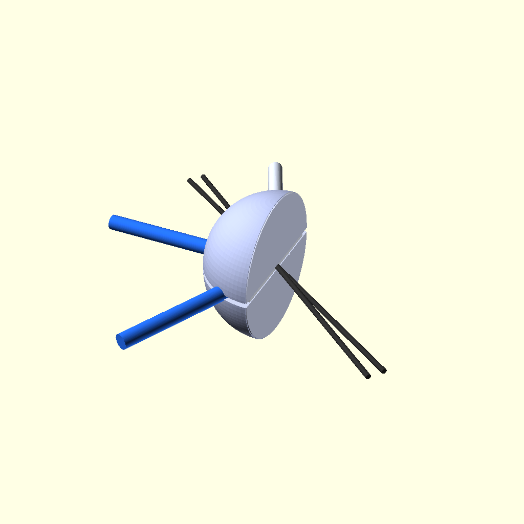
Cross-section — two solid crystal hemispheres with side-glow fibres (blue) and end-glow fibres (clear) at the equator. No electrical wiring reaches the crystal.
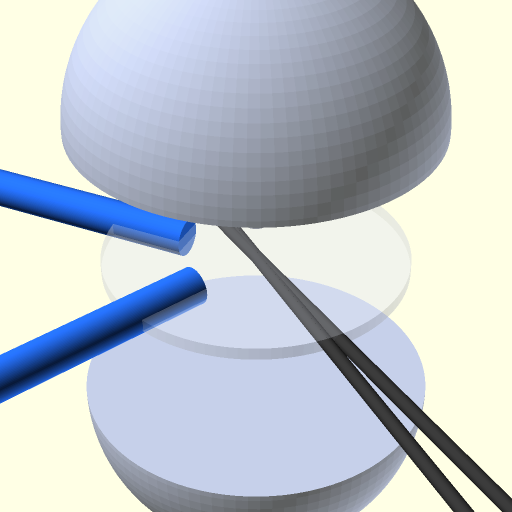
Exploded view — bottom hemisphere (flat face up), components at equator, top hemisphere placed on top.
External precedent — Heatherwick Studio, Bleigiessen (2004):
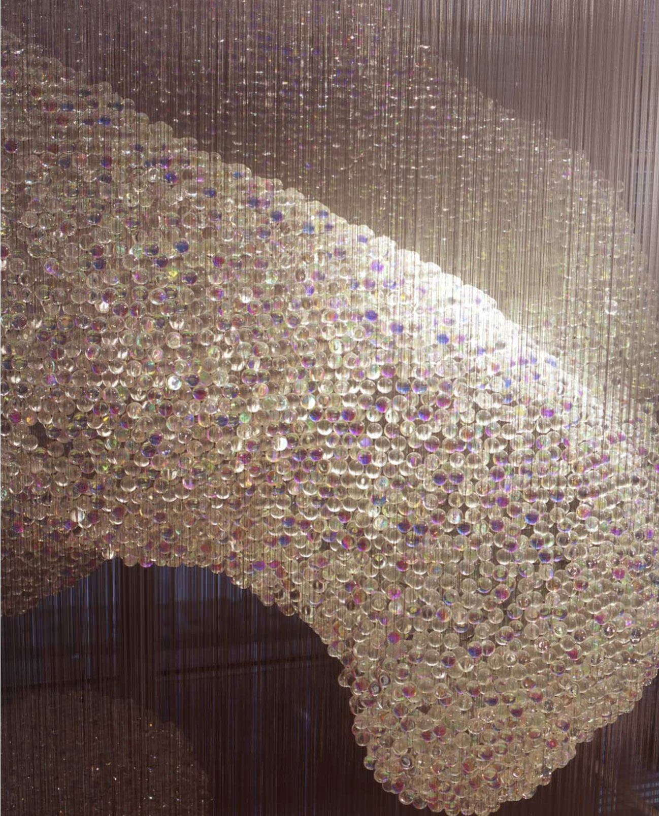
Thousands of glass crystals on invisible lines forming a floating sculptural volume. The construction technique closely parallels our approach.
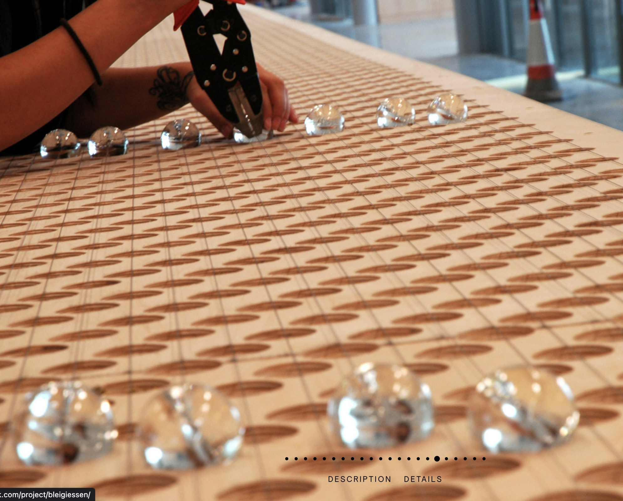
Fabrication — crystals laid out on a jig board at precise intervals, similar to our workshop assembly process (see B.8).

A single Bleigiessen glass crystal — dichroic coating produces iridescent colour shifts as the viewing angle changes.
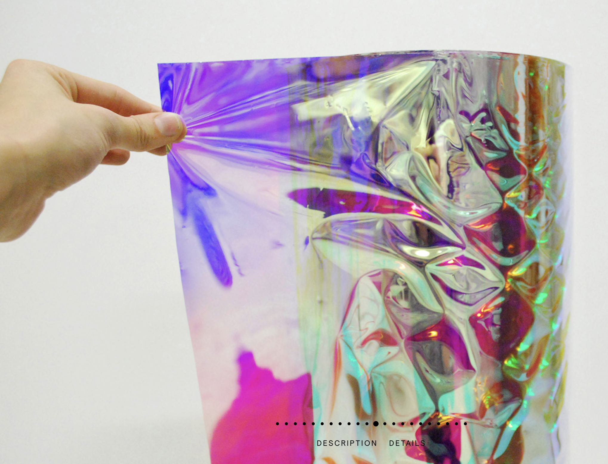
Dichroic film material — self-adhesive film or flakes can be embedded in resin-cast crystals for colour-shifting effects.
Star colours are real and measurable — determined by surface temperature and quantified by the B-V colour index (the difference in brightness between blue and visual filters). Based on Charity (2001) and Harre & Heller (2021), “Digital Color Codes of Stars”, the true perceived colours of stars are subtler than popular culture suggests — there are no truly green or deep-red stars. “Red” giants like Betelgeuse actually appear deep orange.
| Colour Group | Spectral Class | B-V Range | True Colour (Hex) | Example Stars | Count |
|---|---|---|---|---|---|
| Blue-white | O, B | −0.33 to −0.02 | #aabfff | Rigel, Spica, Regulus | ~60 |
| White | A, early F | −0.02 to +0.30 | #cad7ff | Sirius, Vega, Altair | ~72 |
| Pale cream | Late F, G | +0.30 to +0.81 | #fff4ea | Procyon, Capella | ~67 |
| Orange | K | +0.81 to +1.40 | #ffd2a1 | Arcturus, Aldebaran, Pollux | ~42 |
| Deep orange | M | +1.40 to +2.00 | #ffcc6f | Betelgeuse, Antares | ~30 |
| Total crystals (12 constellations) | 150 | ||||
We propose a tiered material strategy that puts the most impressive materials where visitors look closest, and cost-effective materials where they don’t:
| Tier | Stars | Material | Size | Rationale |
|---|---|---|---|---|
| 1 — Navigator Stars | 10–15 (brightest) | Preciosa Czech crystal faceted rounds + optional Bristol Blue commissions | 8–12mm | These are the stars people examine closely on the plinth. Maximum sparkle and prismatic fire. |
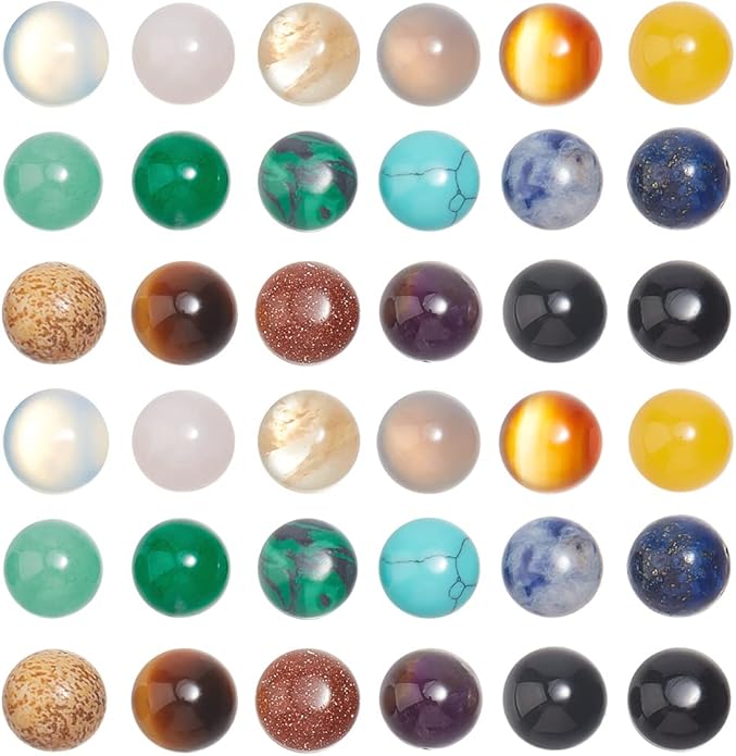
| 2 — Named Stars | 40–60 (mag ≤2) | Natural gemstone crystals (clear quartz, citrine, carnelian, blue topaz) with 1.5mm pre-drilled holes — fits the fibre directly | 6–10mm | Real gemstones add authenticity; each star is a genuine semi-precious stone. Sourced from Crystals of Cambay (1.5mm hole gemstones, no reaming needed). |
| 3 — Background Stars | 150–200 (mag 3–5) | Chinese crystal glass or quality acrylic faceted crystals | 4–6mm | Illuminated from within but not closely inspected at ceiling height. Acrylic has matched refractive index (1.49) with PMMA fibre for optimal optical coupling. |
| 4 — Special Effect | 5–10 (variable/notable) | Resin-cast with embedded dichroic film flakes | 8–14mm | Unique colour-shifting shimmer for stars like Betelgeuse (known variable star). Cast in silicone moulds with custom through-holes for the fibre. |
| Colour Group | Crystal (Preciosa) | Gemstone | Acrylic |
|---|---|---|---|
| Blue-white | Sapphire, Light Sapphire | Blue Topaz, Aquamarine | Transparent Sapphire |
| White | Crystal Clear, Crystal AB | Clear Quartz (Rock Crystal) | Transparent Crystal |
| Pale cream | Light Colorado Topaz, Champagne | Citrine, Lemon Quartz | Transparent Champagne |
| Orange | Topaz, Sun, Fire Opal | Carnelian, Amber | Transparent Amber |
| Deep orange | Hyacinth, Light Siam | Red Carnelian, Hessonite Garnet | Transparent Hyacinth |
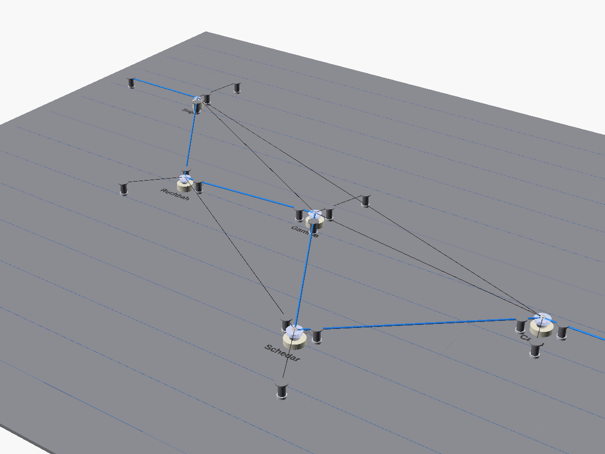
Each constellation’s star positions must be held rigid in tension. The structural bracing lines that triangulate the constellation are generated using Delaunay triangulation — a mathematical algorithm that creates the optimal set of triangles from any set of points, ensuring rigidity with minimum lines.
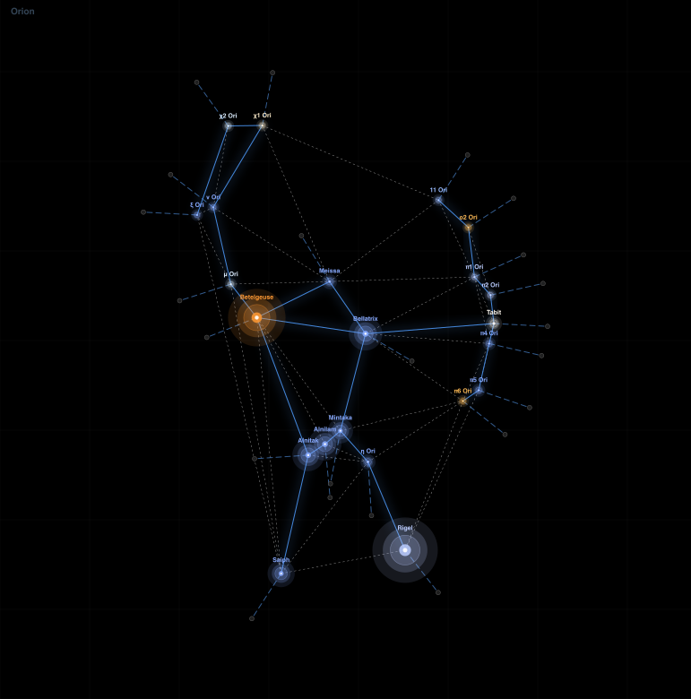
Orion (22 stars) — the most complex constellation of the 88. Blue dotted lines are end-glow fibre (invisible, carrying light to each crystal). Solid blue lines are side-glow fibre (the visible constellation edges). Grey dotted lines are nylon monofilament bracing where additional structural support is needed without a light path.
In the current approach, every structural line is 1.5mm end-glow fibre optic, giving each crystal its own dedicated light supply from the twinkle engine. This eliminates the need for separate bracing lines — the fibre simultaneously provides structure and light delivery. Each crystal sits at a junction where one or more fibre ends are epoxied into the crystal sandwich, with light entering through the cut fibre end.
Nylon monofilament (black fishing line) is used as structural bracing where additional support is needed without a light path. Where bracing lines pass through a TECNI® TG1.5 gripper, the monofilament must be 1.5mm diameter to match the gripper’s cable bore; internal bracing between crystals could be thinner if 1.5mm looks too visible, but this will be assessed during prototyping. Monofilament bonds well with epoxy and is near-invisible in the dark.
We have validated every constellation’s structural stability using a spring-tension simulation: 87 of 88 pass with zero displacement under perturbation, and the remaining one (Circinus) is within 2.2mm tolerance.
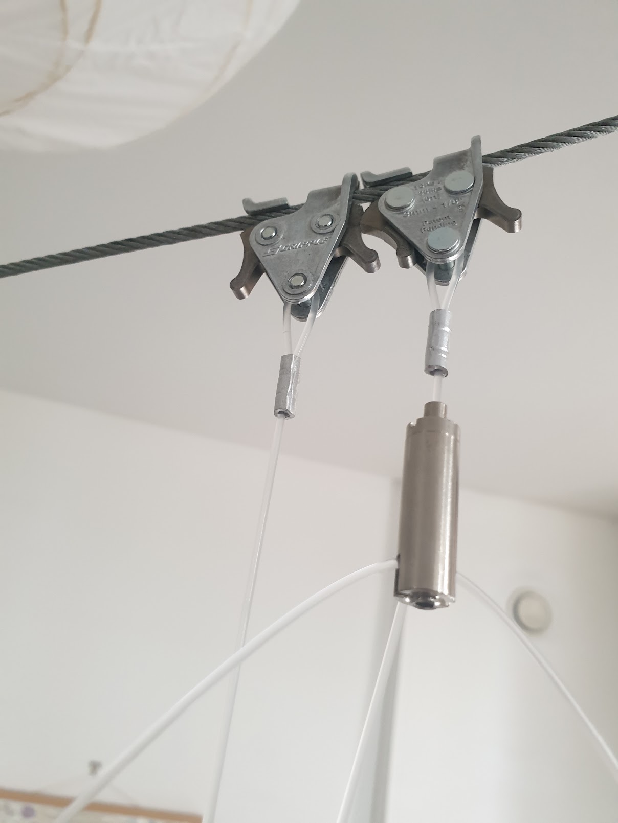
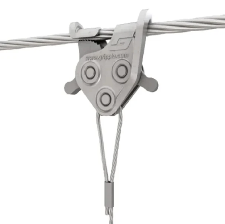
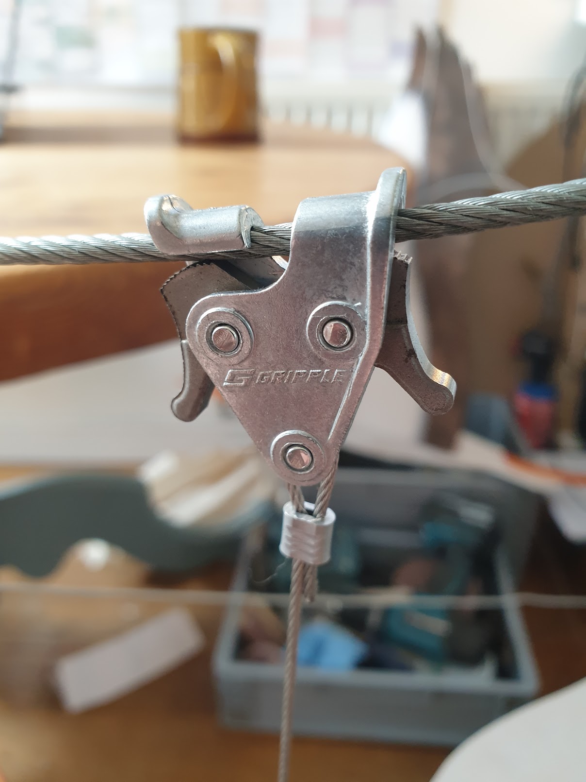
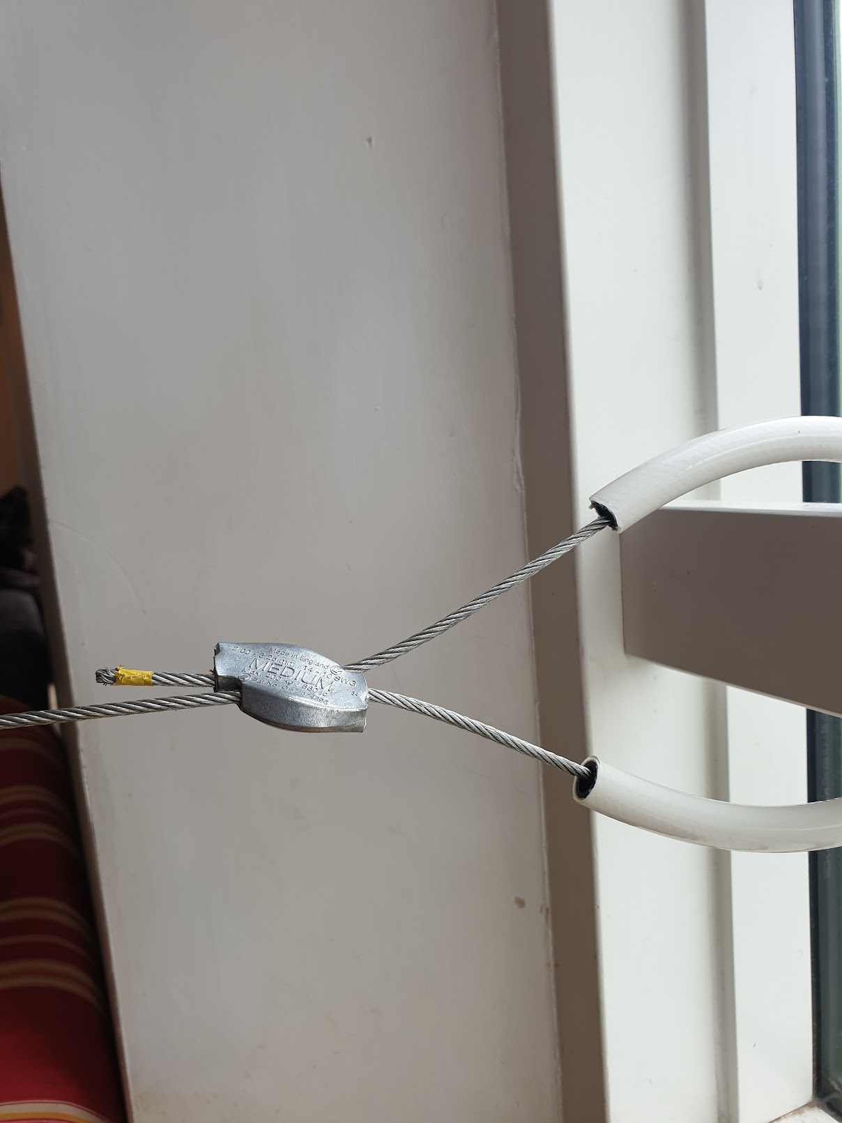
TECNI® V-Gliders on 3mm stainless steel cable at the White Storks installation, attached via a Gripple C-Clip. The 1.5 mm Gripple Invisigrip suspension cable (identical in material and dimension to side-glow fibre) was used here for its near-invisibility to support bird wing armatures. The same component family is used in our constellation rigging — substituting threaded M6 grippers for V-Gliders, and adding LED illumination.
Each constellation is illuminated by a single 12V DC twinkle engine — a compact 16W RGBW fibre optic illuminator that feeds all the constellation’s end-glow fibres simultaneously. All fibres from a single constellation bundle into a ferrule that faces the LED die. Light travels through the 1.5mm PMMA end-glow fibre, routed along the beam from the engine to each mount point, then dropping down to the crystal. The cut fibre end is epoxied into the crystal sandwich, delivering light directly. There are no LEDs at the anchor mounts or inside the crystals — all light originates at the engine.
With 150 star crystals across 12 constellations, the installation requires 12 twinkle engines (one per constellation). Star colour comes from tinted or coloured crystals, not from LED colour — a single white LED per engine illuminates all stars in the constellation, with the crystal material providing the colour filter.
The TECNI® angled glider is the core component that holds each fibre optic line under tension. Its universal pivot joint between the M6 female mounting thread and the gripper body allows the gripper to swing freely and align with the cable direction — essential because constellation lines fan out radially from each anchor, rarely pulling straight down. Understanding the mechanism is important because it determines how the entire rigging system assembles and adjusts.
Inside the gripper body is a cone-shaped bore that narrows towards one end. Sitting inside this cone are three hardened steel ball bearings arranged symmetrically around the cable. When the cable is pulled downward (under load), the balls are drawn into the narrow end of the cone, wedging tighter against the cable — the harder the pull, the stronger the grip. This is a self-locking mechanism: load increases grip force automatically.
To release or adjust the cable, a spring-loaded plunger tube at the top of the gripper is pushed down. This forces the ball bearings back into the wider part of the cone, relieving their grip on the cable and allowing it to slide freely. Release the plunger and the balls re-engage immediately. This gives infinite, tool-free adjustment of cable position — push the plunger, slide the cable, release.
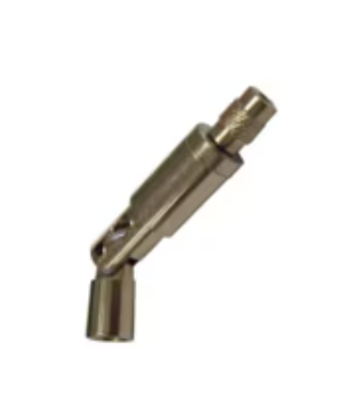
TECNI® TG1.5 Angled Glider (170.015.009) — universal pivot allows the gripper to follow the cable direction.
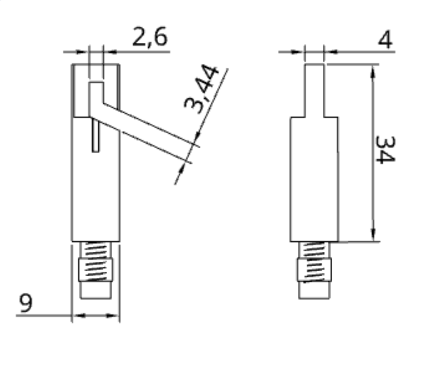
Technical drawing — 34mm body, 9mm M6 female thread, universal pivot at centre. Same ball-bearing cone mechanism as all TG1.5 variants.
| Specification | TECNI® TG1.5 — M6 Female Angled Glider |
|---|---|
| Product code | 170.015.009 |
| Cable diameter | 1.5mm (7×7 construction) |
| Working load limit | 15kg (1.5mm cable, per TECNI data sheet V2023-01) |
| Dimensions | 34mm body + 9mm M6 thread = 43mm overall |
| Thread | M6 female (screws onto male-stud pot magnet) |
| Pivot | Universal joint — free rotation to follow cable angle |
| Cable exit | Side exit through plunger |
| Adjustment | Infinite, tool-free (push plunger to release, slide cable, release plunger to lock) |
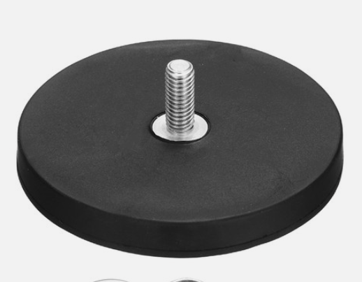
Rubber-coated neodymium pot magnet with M6 external (male) stud. The TECNI® angled glider’s M6 female thread screws directly onto the stud.
The primary anchor magnet is a rubber-coated neodymium pot magnet with M6 external (male) stud. The rubber (TPV) coating protects painted steelwork from scratching, while the M6 stud accepts the angled glider’s female thread directly. Because the actual load per anchor is only ~200g, we can use a compact 32–36mm magnet rather than the larger 66mm size — even 10kg rated pull gives a 50× safety margin. Smaller magnets are cheaper, lighter, and less visible.
| Specification | 32–36mm Rubber-Coated M6 Stud Pot Magnet |
|---|---|
| Dimensions | 32–36mm diameter × 7–9mm tall |
| Magnet material | NdFeB (neodymium iron boron), N35–N42 grade |
| Coating | Black or white TPV rubber |
| Thread | M6 external (male) stud, 8–10mm length |
| Pull force (direct) | 10–22 kg on bare steel; ~6–13 kg derated for paint |
| Actual load per anchor | ~200g (50–65× safety margin) |
| Weight | ~30–60 g |
| Max operating temp | 80°C |
| Compliance | RoHS, REACH |
A stainless extension spring connects the pot magnet to the TECNI® angled glider, absorbing thermal expansion and vibration. An M6 eye nut screws onto the magnet’s male stud; the spring hooks into this eye and into an M6 eye bolt that threads into the glider’s M6 female bore. The angled joint allows lines to pull at any angle without side-loading the magnet — critical because fibres radiate outward from the anchor, rarely pulling straight down. The anchor assembly comprises four off-the-shelf components:
Every anchor is a fibre anchor: a TG1.5 grips 1.5mm end-glow fibre. The fibre routes along the beam back to the constellation’s twinkle engine, carrying light from the engine down to the crystal at the far end. No LED sits at the anchor itself. Multiple fibres can share a single pot-magnet mount using a gripper stack, keeping the number of physical anchor positions manageable.

Anchor assembly — pot magnet, extension spring (with M6 eye nut and eye bolt), and TECNI® angled glider. 1.5 mm end-glow fibre enters the side exit and exits the plunger nipple. The spring absorbs thermal movement; the angled joint allows off-axis loads.

Exploded view — steel beam, rubber-coated pot magnet (M6 stud), M6 eye nut, stainless extension spring, M6 eye bolt, TECNI angled glider, 1.5 mm end-glow fibre optic.
Rigging process:
Where no suitable flat steel surface is available for a pot magnet — for example, anchoring onto an existing 3mm stainless steel catenary cable or similar infrastructure — the TECNI® TG1.5 Eye Glider (170.015.010) or Hook Glider with latch (170.015.003) provide alternatives. The gripper mechanism is identical (same ball-bearing cone, same 1.5mm cable capacity), but instead of an M6 thread the eye glider has a Ø10mm eye ring (or the hook variant a spring-loaded hook with safety latch). Either connects to a Gripple C-Clip on the support cable via a stainless extension spring (hook ends into the C-Clip bottom slot and the eye ring), absorbing thermal movement and locking the gripper at a fixed position along the cable length.
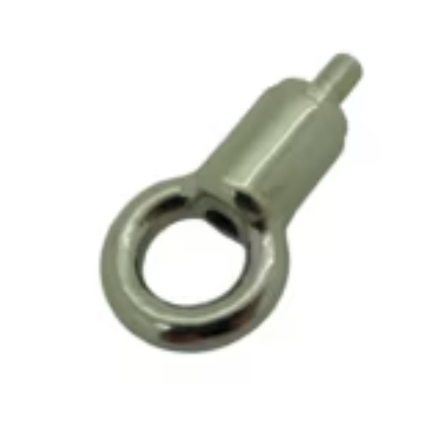
TECNI® TG1.5 Eye Glider (170.015.010).
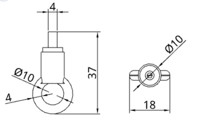
Dimensions: 37mm total height, 18mm body width. Ø10mm eye ring, 4mm wire.
| Specification | TG1.5 Eye Glider |
|---|---|
| Part number | 170.015.010 |
| Total height | 37mm |
| Body width | 18mm |
| Eye ring | Ø10mm inner, 4mm wire |
| Cable diameter | 1.5mm |
| WLL (1.5mm cable) | 15kg (per TECNI data sheet V2023-01) |
| WLL (1.2mm cable) | 12kg |
| WLL (1.0mm cable) | 8kg |
The eye glider is the preferred cable-mount option: the closed eye ring cannot accidentally detach, and is the most economical variant. A hook glider with latch (170.015.003) is available as an alternative where faster on-site clip-on/clip-off is needed. Both variants use the same infinite-adjustment gripper mechanism as the M6 threaded version.

Cable anchor assembly — the Gripple® C-Clip clamps onto the 3 mm catenary cable; an extension spring connects the C-Clip to the TECNI® eye glider. Fibre enters the side exit and exits the plunger nipple, routing along the cable to the twinkle engine.

Exploded view — 3 mm catenary cable, Gripple C-Clip (CC3), stainless extension spring, TECNI eye glider (170.015.010), 1.5 mm end-glow fibre optic.
PMMA end-glow fibre has negligible elasticity (~1% elongation at break). Over a typical 3–5 m fibre run, even modest thermal movement of the steel structure (±1–2 mm seasonal, plus vibration from foot traffic and wind) would transmit directly to the crystal and anchor hardware if the fibre path were rigid. A stainless extension spring at every anchor point absorbs this movement, keeping the fibre under gentle tension without risk of fatigue or detachment.
Two configurations are used, matching the two anchor methods:
The springs are standard stainless steel extension springs (6–8 mm OD, ~25 mm body length, hook ends). At the loads involved (<0.5 kg per fibre), the spring provides a very soft compliance — enough to decouple the fibre from structural movement without adding visible sag.
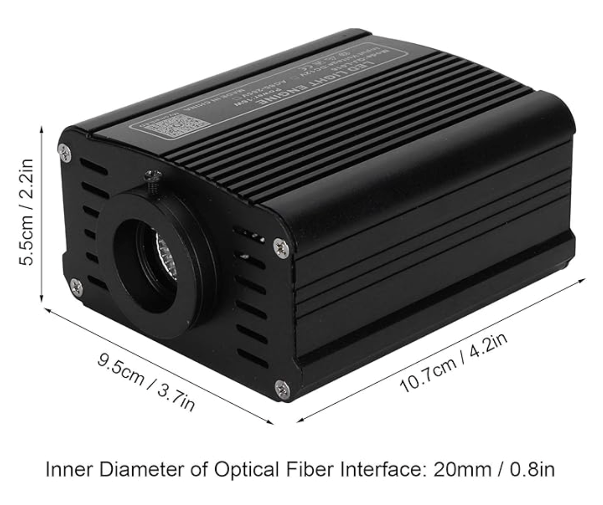
16W RGBW twinkle engine — CREE LED, ~20mm fibre port, built-in twinkle wheel and driver. 107×95×55mm. RF remote + Bluetooth app control.
A fibre optic twinkle engine (also called a light source, illuminator, or bundle injector) is a self-contained unit that couples LED light into multiple optical fibres simultaneously. These are an established product category — widely used in starfield ceilings, fibre optic chandeliers, pool lighting, and architectural installations. The engine contains everything needed: LED, driver, heatsink, reflector optics, and a fibre port where the cut ends of the fibres face the LED die.
A 16W CREE RGBW LED is mounted on an aluminium heatsink inside the enclosure. A reflector or TIR lens collects the LED’s wide-angle output and concentrates it onto the fibre port — a circular opening (typically ~20mm diameter) where the polished ends of all the fibres are presented in a tight bundle. Light enters each fibre within its acceptance cone (NA ~0.50, half-angle ~30°) and travels down the core by total internal reflection.
The engine runs on 12V DC from the shared PSU, connected via a 2-pin waterproof plug. A single engine illuminates an entire constellation.
Most engines include a twinkle wheel — a slowly rotating disc with irregular cutouts positioned between the LED and the fibre port. As the disc turns, different fibres are intermittently shadowed, causing individual stars to flicker and scintillate realistically. The speed and pattern are adjustable via RF remote. This mechanical effect is simple, reliable, and produces a far more convincing stellar twinkle than electronic PWM dimming of individual LEDs.
The largest constellation is Orion with 22 stars, so the engine must handle up to 22 fibres. The bundle geometry:
We will fabricate a concentrating ferrule — a tapered brass adapter (~20mm at the engine face narrowing to ~8mm at the fibre bundle face) with polished internal surfaces that funnel light onto the small bundle. This could increase per-fibre brightness by 3–5× compared to an open port. We will prototype ferrules using turned brass tube.
| Specification | 16W RGBW Twinkle Engine |
|---|---|
| Power | 16W (CREE RGBW LED) |
| Voltage | 12V DC (powered from shared 12V PSU) |
| LED colour | RGBW — white for star illumination; colour available for effects |
| Port diameter | ~20mm (18–20mm common bundle port) |
| Effects | Twinkle wheel (adjustable speed), multiple presets, RF remote + Bluetooth app |
| Body | ~107 × 95 × 55mm, ~0.3kg |
| IP rating | Indoor (IP20) — housed in IP65 enclosure with PSU on site |
With 12 engines at 16W each, total 12V power is approximately ~192W. Each constellation draws ~21W at 12V (engine + audio module), supplied by its own weatherproof 12V PSU (Mean Well LPV-35-12, 36W capacity).
Almost no fibre optic twinkle engine ships with an IP rating above IP20 (indoor only). The dry dock environment is covered but not climate-sealed — damp patches exist at floor level. Our approach: house each engine inside a standard IP65 ABS enclosure with cable glands for fibre bundle exit and power entry. The compact 16W engine (107×95×55mm) fits comfortably inside. The enclosure sits inside the story plinth (see B.8), keeping it accessible but protected. The fibre bundle exits the top of the plinth and runs up to the constellation, secured along steel beams with magnetic cable clips every ~0.5m.
Each end-glow fibre runs: engine → along beam → mount point → drop to crystal. The beam routing section adds significant length, but end-glow fibre transmits zero light along its length, so the routing is invisible even when lit. We use 1.5mm bare (unsheathed) PMMA end-glow fibre — the same diameter as the side-glow fibre, and compatible with the TG1.5 gripper at every mount point.
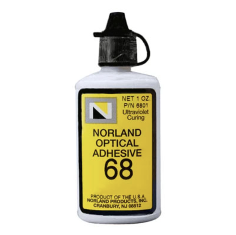
Norland NOA 68 UV optical adhesive — bonds PMMA to glass with matched refractive index. ~48 kg pull-out strength per fibre (10 MPa shear × ~47mm² contact area).
Each crystal sandwich is sealed with UV-stabilised two-part clear epoxy, bonding the cut fibre ends into the crystal halves and providing a moisture seal. The main long-term concern is yellowing. We mitigate this by:
The dock structure consists of steel beams running perpendicular to the ship, joined by glass beams that drop below the steel. Constellations are mounted using:
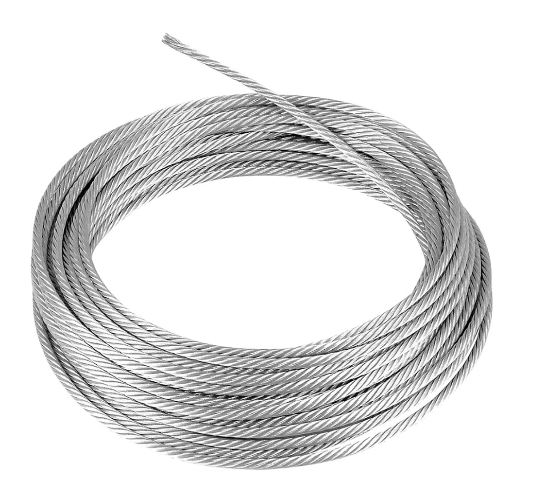
3mm stainless steel wire rope — breaking load ~756 kg. Used for catenary lines between beams.
Gripple® C-Clip (CC3) — SWL 15 kg. Twist-on/off clamp for creating anchor points anywhere along a catenary wire.
Where anchor points do not fall in exactly the right position, we run a 3mm or 6mm Gripple catenary wire between two fixed points and use Gripple C-Clips to create adjustable anchor positions at any point along the span. The C-Clip is a twist-on/off device that locks solidly onto the catenary wire via internal cams, providing both horizontal and vertical adjustment — it can be repositioned freely before locking, and fitted retrospectively without re-threading the cable.
Gripple C-Clip on 3mm catenary wire — twist-on clamp provides an adjustable anchor point anywhere along the span. Drop cable hangs vertically from the clip.
The catenary wires themselves need anchoring at each end. Where beams or columns are available, the 3mm cable is looped around the beam and the two ends are joined and tensioned using a Gripple Plus Medium connector. A length of flexible hose or rubber sleeving is threaded onto the cable at the contact point to protect the beam’s painted surface from marking — the cable never touches the steel directly.
Gripple Plus Medium joining a 3mm cable looped around a beam. White hose sleeving protects the beam surface from cable contact.
The Gripple Plus is a wire joiner and tensioner in one — both wire ends feed into opposite sides of the body, and internal ceramic cam rollers grip the wire under reverse tension. Tensioning is done with a standard Gripple tensioning tool (10:1 mechanical advantage). The connector is fully reusable — a release key unlocks the cams for repositioning or removal.
| Specification | Gripple Plus Medium |
|---|---|
| Wire range | 2.00–3.25mm |
| Safe working load | 400kg |
| Mechanism | Ceramic cam rollers (patented) |
| Reusable | Yes (with release key) |
Safety factor: We apply a 10× safety factor, consistent with EU entertainment rigging practice. Paint on the steel beams reduces magnetic pull force by approximately 40%. A 32–36mm rubber-coated pot magnet (10–22kg rated) derated by 40% for paint gives ~6–13kg effective pull. Each individual anchor carries only ~30–80g, giving an actual safety factor of 75–430×. Each constellation weighs well under 500g total. With many anchor points per constellation and a longitudinal safety line linking them all, the system is highly redundant even with single magnets.
The steel beams are rectangular hollow section (RHS) with no accessible flange or gap to pass straps or loops around. This rules out conventional beam clamps, G-clamps, and wrap-around straps. Magnets are the only viable non-invasive, non-marking, fully reversible attachment method for these beams.
Each constellation is powered by a single weatherproof 12V PSU that feeds the LED twinkle engine and a compact 12V SD-card audio module with speaker. The mains circuit uses CEEform connectors throughout (IP44, standard stage/site electrics) — no exposed mains sockets, no power bricks, no USB adapters. All connections at constellation level are 12V SELV (Safety Extra Low Voltage), eliminating IP rating concerns for downstream wiring.
| Component | Count | Power Each | Subtotal |
|---|---|---|---|
| LED twinkle engines (12V DC) | 12 | ~16W | ~192W |
| 12V audio modules + speakers | 12 | ~5W | ~60W |
| Total 12V load | ~252W | ||
| Mains draw (at ~85% PSU efficiency) | ~296W (~1.3A at 230V) | ||
Total mains draw: ~296W. At 230V that is ~1.3A — comfortably within a single 13A circuit, with substantial headroom.
The twinkle engines are 12V DC devices. Rather than plug each engine’s individual mains adapter into an exposed mains socket (which would not be IP-rated), we use a single weatherproof 12V PSU per constellation that powers both the engine and the audio module. This keeps all mains connections inside IP44 CEEform plugs and sockets, with only safe 12V wiring at constellation level.
A key-operated isolation switch at the mains entry point gives venue staff daily on/off and emergency shutdown control.
Mains power is taken from the existing electrical outlet at the centre of the stern wall (directly behind the ship) and distributed via a full perimeter loop around the dock, running along the steel beams. All mains-level connections are mounted at beam height, well above the floor.
Full power hierarchy:
Cable runs are secured along the steel beams using magnetic cable clips, keeping everything tidy and off the floor. Each PSU can be disconnected individually for maintenance without affecting the rest of the installation.

Wiring diagram — top: indicative cable route around the full dock perimeter (orange = 230V mains loop, green = constellation positions). Power inlet at centre of stern wall. Bottom: electrical hierarchy from mains to 12V PSU to LED engine + audio module. All positions subject to site survey.
| Cable Run | Gauge | Type | Carries |
|---|---|---|---|
| Mains loop (along beams, full dock perimeter) | 3G1.5mm² | H07RN-F heavy-duty rubber flex | ~1.3A at 230V AC |
| PSU to engine + audio (per constellation) | 2-pin IP65 waterproof DC connectors (no separate cable) | ~1.8A at 12V DC | |
All connections are tool-free and fully reversible:
Because the entire mains circuit is assembled from pluggable, pre-made components (CEEform plug, inline RCD, CEEform Y-splitters, IP67 PSUs with sealed flying leads), it is classified as portable appliance assembly rather than a fixed or temporary electrical installation. This significantly simplifies the regulatory position:
Each constellation is pre-assembled in the workshop as a complete tensile unit before being transported to site. The assembly jig is a large mild steel sheet (approx. 1220×2440mm). The process:
Assembly jig — Cassiopeia layout on mild steel sheet. Plastic pipe pucks hold crystal halves at each star position, magnetic clamps tension fibres and bracing lines.
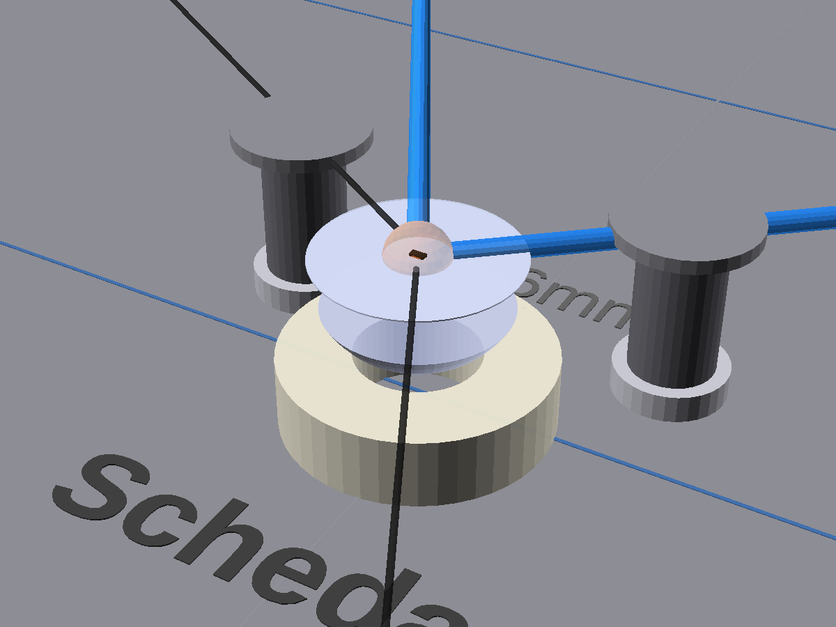
Detail: Schedar (α Cas, mag 2.24) — larger crystal in shorter puck with converging fibres.
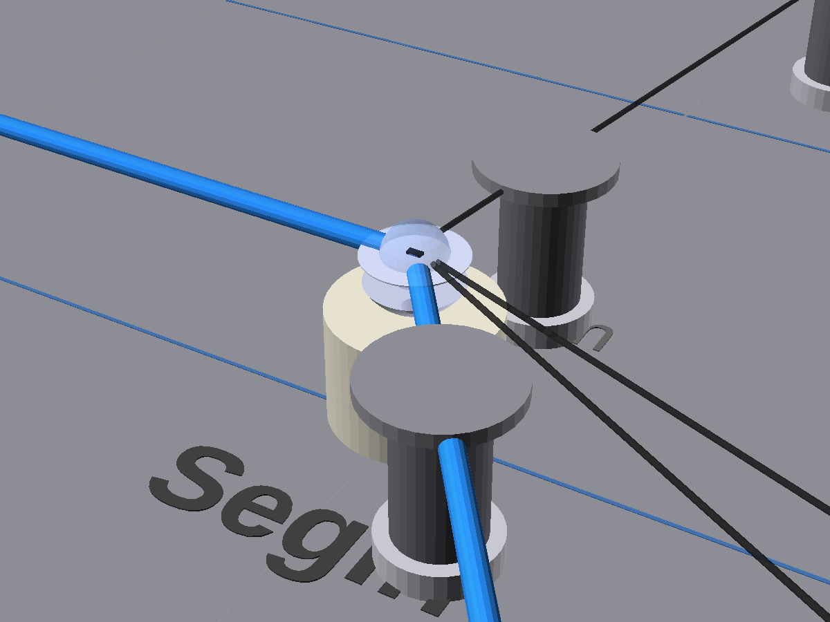
Detail: Segin (ε Cas, mag 3.37) — smaller, dimmer star in taller puck.
Each constellation is accompanied by a freestanding story plinth on the dock floor below it.
A compact wedge-shaped lectern built from 12mm MDF, painted matt black (sealed and primed before painting). The angled reading surface (~30–40°) is a Perspex top with printed vinyl applied, internally backlit by a small 12V LED strip or puck light. The graphics glow through the vinyl, making the plinth readable in the dark dock environment.
All electrical components inside the plinth are housed in their own IP65 Wiska-style enclosures with cable glands and waterproof connectors, so the MDF body does not need to be IP-rated itself. The plinth contains: the twinkle engine in an IP65 ABS box, the 12V PSU (already IP67), the audio module and speaker in an IP65 box, and the backlight LED. A CEEform 16A inlet on the side connects to the mains loop. The fibre bundle exits the top and runs up to the constellation above.
An internal MDF shelf halfway up provides structural rigidity and separates the electronics compartment below from the backlight cavity above.

Cross-section (side view) — frosted perspex lid lifts off to reveal the equipment shelf. PSU connects to twinkle engine, audio/speaker box, and LED backlight via waterproof 12 V connectors. CEEform 16 A male inlet on the back panel accepts the mains loop cable. Fibre bundle exits through the back wall and routes up to the constellation.
Adjustable rubber levelling feet at each corner. Low enough for children and wheelchair users to read comfortably. No wall-mounting — the dock walls are pennant rubble stonework, a Scheduled Monument, and must not be drilled.
Each constellation’s 12V PSU feeds a compact 12V MP3 decoder/amplifier board with a small speaker, housed inside an IP65 Wiska-style enclosure within the story plinth. Each unit auto-plays the same ambient track from a pre-loaded micro SD card on power-up. No separate cables, no WiFi, no Bluetooth pairing — the audio runs directly from the shared 12V supply alongside the twinkle engine.
Each unit is a 12V MP3 decoder board with built-in class-D amplifier (2×5W) driving a small 40mm 4Ω speaker. The board runs natively on 12V DC — no voltage conversion needed. It accepts a micro SD card (FAT32, up to 32GB) and auto-plays on power-up, remembering its last playback mode (loop all / repeat one) across power cycles. An included IR remote is used once during setup to set volume and loop mode. The board and speaker are assembled inside an IP65 ABS junction box with a circular hole cut in the lid for speaker output, mounted inside the plinth.
All 12 units are powered from the same mains loop, switched on simultaneously by the shared timer / smart switch. Each board auto-plays on power-up, so all stations begin their track at the same moment. Over time, minor clock drift between modules is imperceptible because the music is ambient and non-rhythmic — gentle pads and textures rather than beats. Any slight phase offset actually enriches the spatial quality, creating a diffuse, immersive sound field as visitors move through the dock.
Volume is set once per unit using the included IR remote control, keeping levels low enough to sit beneath the dock’s natural soundscape of wind, water, and stone. The result is subtle and atmospheric — visitors notice the music when they pause at a constellation, but it never overwhelms. The ambient, looping nature of the track also makes it suitable for sensory-sensitive visitors.
A single seamless-loop ambient track (2–10 minutes) stored as an MP3 on a micro SD card. The track could be commissioned or sourced royalty-free. Because each SD card is independently loaded, different constellations could carry different tracks in future if desired — just swap the SD card.
Quantities shown are estimates based on the 12 selected constellations. Exact quantities, scale, and spacing will be determined during prototyping.
| Constellation | Stars | Side-Glow (m) | End-Glow (m) | Rig (hrs) |
|---|---|---|---|---|
| Orion | 22 | 9.4 | 110 | 5.8 |
| Ursa Major | 19 | 7.2 | 95 | 5.2 |
| Scorpius | 18 | 5.8 | 90 | 4.2 |
| Gemini | 17 | 5.7 | 85 | 4.7 |
| Leo | 13 | 6.0 | 65 | 3.2 |
| Pegasus | 13 | 5.3 | 65 | 2.9 |
| Taurus | 12 | 3.2 | 60 | 3.0 |
| Canis Major | 10 | 4.0 | 50 | 2.3 |
| Cygnus | 10 | 4.2 | 50 | 2.3 |
| Ursa Minor | 7 | 2.7 | 35 | 1.2 |
| Cassiopeia | 5 | 1.4 | 25 | 0.9 |
| Crux | 4 | 0.7 | 20 | 0.8 |
| TOTAL | 150 | ~56 m | ~750 m | ~37 hrs |
* End-glow fibre assumes ~5m per crystal (2–3m beam routing + 2–3m drop to crystal). Side-glow lengths are constellation edge segments only. Fibre lengths assume constellations scaled to 0.6–1.8m physical span depending on star count.
All costs are estimates — exact material quantities depend on the final constellation selection, scale, and spacing determined during prototyping. Linked unit costs are verified against UK supplier prices (Feb 2026).
| Item | Specification | Qty | Unit Cost | Line Total |
|---|---|---|---|---|
| FIBRE OPTIC MATERIALS | ||||
| 1.5mm PMMA side-glow fibre | 100m reel, side-emitting (visible constellation edge segments). Includes spare. | 100 m (1 reel) | £0.68/m | £68 |
| 1.5mm PMMA end-glow fibre | Injector-to-crystal runs (~5m avg per crystal) + structural bracing. 10 reels = 1000m, ~10% spare. | 1000 m (10 reels) | £0.40/m | £400 |
| UV-cure optical resin | Norland NOA 68 (1oz bottles). Bonds PMMA to glass with matched RI. Third bottle as spare. | 3 | £33 | £99 |
| Concentrating ferrules (engine end) | 8mm brass round tube (1m length), cut to ~20mm ferrules. Bundles end-glow fibres into engine port. Workshop-fabricated, includes spares. | 1m tube | £7 | £7 |
| STAR CRYSTALS | ||||
| Star crystals, 14mm | Glass, acrylic, quartz, or semi-precious stone — assorted colours matching B-V index (material TBC after prototyping). 300 hemispheres for 150 sandwich assemblies + 45 spares/bright-star extras. | 345 | £0.80 | £276 |
| Clear 2-part epoxy | Gorilla Epoxy 25ml syringe tubes. Bonds crystal halves around fibre ends (sandwich assembly). ~50 crystals per tube. | 6 | £7 | £42 |
| Cerium oxide polishing compound | Cerium oxide + felt pad kit. Polishes crystal faces after cutting for maximum light transmission. | 1 kit | £9 | £9 |
| STRUCTURAL HARDWARE | ||||
| TECNI® TG1.5 Grippers (mixed) | ~165 needed + 15 spares. Mix from TECNI cable fittings range: M6 threaded gliders (170.015.006, £3.34), hook gliders with latch (170.015.003, £4.15), and angled gliders (170.015.009, £3.41) as needed. Exact mix TBC after site survey. | 180 | £3.50 avg | £630 |
| 31mm rubber-coated pot magnets | Neodymium, M6 external stud, ~25kg pull. Used where flat steel is available; not every anchor needs one — some anchor onto catenary cables via hook gliders or Gripple C-clips instead. Exact qty TBC after site survey. +10 spares. | 80 | £4.50 | £360 |
| 1.5mm black nylon monofilament | Fishing line for structural bracing (grey dotted lines in diagrams). 1.5mm to fit TECNI® TG1.5 grippers where bracing attaches to beams | 100 m | £0.04/m | £4 |
| 1.5mm stainless wire rope | For external anchor runs to dock beams | 100 m | £0.36/m | £36 |
| Wire rope connectors | Copper ferrule crimps (1.5mm Talurit) | 250 | £0.08 | £20 |
| Longitudinal safety line | 1mm stainless wire rope, runs along beams linking anchor points in series (secondary retention). | 100 m | £0.10/m | £10 |
| Safety line cable clips | Stainless cable clips (100-pack), secure safety line to beams. | 100 | £0.04 | £4 |
| B-Lock braided cable | Stainless braided cable for extending mounting points between beams. | 30 m | £0.24/m | £7 |
| Gripple connectors (medium) | Gripple Medium (bags of 20). Inline tensioners for braided cable runs. | 35 (2 bags) | £0.90 | £32 |
| Column clamps / hooks | For anchoring to upright columns | 30 | £3.60 | £108 |
| Hose sleeving (beam protection) | Short lengths of 8mm black rubber hose threaded onto 3mm catenary cable where it loops around beams, preventing cable from marking painted steelwork | 5 m | £1.70/m | £9 |
| Stainless extension springs | 304 SS tension springs, 0.5×5mm, hook ends (10-packs). One per gripper anchor point, absorbs thermal expansion and vibration (~3mm travel). +15 spares. | 180 (18 packs) | £0.30 | £54 |
| M6 eye nuts | 304 SS M6 lifting eye nuts (10-packs). Screws onto pot magnet stud; spring hooks into the eye. +10 spares. | 80 (8 packs) | £0.80 | £64 |
| M6 eye bolts | A4 SS M6 threaded eye bolts. Threads into gripper M6 bore; spring hooks into the eye. Cable-mount anchors use hook-end springs directly (no eyelets needed). +10 spares. | 80 | £1.70 | £136 |
| ELECTRICAL | ||||
| 16W RGBW LED twinkle engines | 12V DC fibre optic illuminator with CREE RGBW LED, twinkle wheel, ~20mm port, RF remote + Bluetooth. All end-glow fibres bundle into port via concentrating ferrule. +1 spare. | 13 | £30 | £390 |
| IP65 ABS enclosures (engine) | IP65 ABS junction box + cable glands. Houses twinkle engine inside plinth (150×110×70mm). +1 spare. | 13 | £10 | £130 |
| Magnetic fibre clips | 8×3mm N52 neodymium disc magnets (100-packs). Small, lightweight magnets to hold single 1.5mm fibre strands against steel beams. Paired with a dab of hot glue or tape as needed. Fibres share routes where possible. | 500 (5 packs) | £0.07 | £35 |
| Cable ties | Assorted cable ties, 1000 pack, for cable management | 1 pack | £17 | £17 |
| Timer / smart switch | Dusk-till-dawn + manual override | 1 | £25 | £25 |
| Key-operated isolation switch | ESP key-operated isolator, mains entry point, allows venue staff to isolate the installation. Key removable in ON and OFF. | 1 | £20 | £20 |
| AMBIENT SOUND (per constellation) | ||||
| 12V MP3 decoder/amp board | Schwamm 12V MP3 decoder with built-in class-D amplifier (2×5W), Bluetooth 5.0, SD card auto-play on power-up, IR remote included. Runs natively on 12V DC. +2 spares. | 14 | £11 | £154 |
| 40mm 4Ω speakers | 40mm full-range 4Ω driver (4-pack), mounted inside IP65 box in plinth. +2 spares. | 14 (4 packs) | £2 | £28 |
| IP65 ABS enclosures (audio) | IP65 ABS junction box (100×68×50mm). Circular hole in lid for speaker output. Houses decoder board + speaker inside plinth. +2 spares. | 14 | £4 | £56 |
| Micro SD cards | SanDisk Ultra 32GB microSDHC, A1 Class 10. Pre-loaded with ambient loop track (MP3). +2 spares. | 14 | £5 | £70 |
| MAINS DISTRIBUTION | ||||
| H07RN-F mains cable (3G1.5mm²) | Heavy-duty rubber flex (CSE Distributors, cut to length), full perimeter loop around dock ~230m + 10m spare for cuts/joins. | 240m | £0.99 | £238 |
| CEEform 16A Y-splitters | PCE 16A 240V soft Y-splitter (IP44) at each constellation position — one side continues loop, other feeds PSU. +1 spare. | 13 | £16 | £208 |
| 12V DC power supplies (IP67) | IP67 36W LED driver with sealed flying leads (no screw terminals). Female CEEform fitted to mains input; 12V output split to 2× male 2-pin waterproof DC connectors feeding engine + audio module. Housed inside plinth. +1 spare. | 13 | £11 | £143 |
| CEEform 16A inline connectors | PCE Shark 16A cable-mount socket (213-6). Fitted to each PSU’s mains input cable, plugging into Y-splitter output. +1 spare. | 13 | £3.50 | £46 |
| 2-pin IP65 waterproof DC connectors | QWORK 2-pin IP65 connector pairs (5-pack). Male on PSU output, female on engine + audio box. All 12V connections pluggable. 6 packs = 30 pairs (+6 spare). | 6 packs | £8 | £48 |
| CEEform 16A blue plug | MK 16A 2P+E single-phase plug, mates with venue socket outlet. +1 spare. | 2 | £8 | £16 |
| Portable RCD unit (30mA) | Masterplug inline RCD, protects entire installation circuit | 1 | £45 | £45 |
| STORY PLINTHS & CONTENT | ||||
| 12mm MDF sheets (plinth shells) | Wickes 12mm MDF (1220×2440mm). ~½ sheet per plinth — front, back, sides, base, internal shelf. Fabricated in-house. +1 spare plinth. | 7 sheets | £24 | £168 |
| 1mm mild steel sheets (plinth bases) | 1mm mild steel (2000×1000mm). Cut to 630×427mm base plates, ~6 per sheet. Adds ballast and stability. | 3 sheets | £54 | £162 |
| MDF-Tite screws | MDF-Tite Tri-Lock Pozi (3.9×40mm, 200-pack) for plinth assembly. | 1 pack | £10 | £10 |
| Perspex sheet (plinth tops) | 3mm clear acrylic, A3, cut to reading surface per plinth. +1 spare. | 13 | £6.50 | £85 |
| Adjustable levelling feet | M8 rubber-pad levelling feet (12-packs with T-nuts), 4 per plinth. +4 spare. | 52 (5 packs) | £0.58 | £35 |
| MDF primer sealer | Rustins Quick Dry MDF Primer (500ml clear). Seals all plinth panels before painting. | 1 | £7 | £7 |
| Matt black spray paint | Industrial spray paint (500ml cans). Covers all 13 plinths. | 4 cans | £6 | £24 |
| PVA wood glue | Everbuild 502 (500ml) for MDF edge joints. | 1 | £7 | £7 |
| 18g brad nails | Tacwise 18g brad nails (25mm, 5000-pack) for MDF panel assembly. | 1 pack | £8 | £8 |
| Plinth backlight | 12V warm white LED puck lights (6-packs). Wired internally from PSU. +1 spare. | 13 (3 packs) | £4 | £52 |
| WORKSHOP JIG | ||||
| Mild steel sheet (1220×2440mm, ~1.5mm) | Jig base — 2–3 sheets, tack-welded for larger constellations | 3 | £110 | £330 |
| Neodymium magnetic clamps | Steel cylinder + disc magnet + washer | 40 | £1.30 | £52 |
| Plastic pipe pucks | 15mm PEX pipe (3m length), cut into short pucks with pipe cutter to hold crystal halves at each star position on jig | 1× 3m | £6 | £6 |
| TOOLS & ACCESS EQUIPMENT | ||||
| 3-legged pruning ladder | Aluminium tripod ladder (suits uneven dock floor) | 1 | £396 | £396 |
| Crimping tool | For wire rope ferrules / Gripple connectors | 1 | £25 | £25 |
| Sharp snips / side cutters | Clean cuts on 1.5mm PMMA fibre ends | 1 | £24 | £24 |
| Fine-grit sandpaper (assorted) | For polishing fibre ends & crystal light release | 1 pack | £10 | £10 |
| Diamond lapping film / wet-dry pads | For flat-lapping crystal hemispheres if cutting crystals in half | 1 set | £15 | £15 |
| Digital multimeter | LAP DC digital multimeter (600V). For continuity, voltage, and PAT checks. | 1 | £10 | £10 |
| Assorted crimp terminals | Draper crimp terminal assortment (150pc, 18-compartment box). For audio, PSU, and 12V connections. | 1 pack | £14 | £14 |
| Subtotal — Materials & Tools | £5,484 | |||
| LABOUR | ||||
| Design & engineering | Star data, structural analysis, component diagrams | 80 hrs | £45/hr | £3,600 |
| Prototyping & R&D | Testing crystal materials, prisms, suncatchers, LED types, fibre coupling | 50 hrs | £35/hr | £1,750 |
| Workshop fabrication | Crystal assembly, fibre prep, gripper attachment, ferrule bundling, testing | 100 hrs | £30/hr | £3,000 |
| On-site rigging | Installation at dry dock (2 riggers) | 37 hrs × 2 | £35/hr | £2,590 |
| Electrical installation | Power distribution, LED wiring, commissioning | 24 hrs | £45/hr | £1,080 |
| PAT testing | Portable appliance testing of assembled mains loop cable and twinkle engines before first use | 1 session | £60 | £60 |
| Stories & research | Navigation history, cultural mythology (Greek, Aboriginal, Arabic, Polynesian), voyage narrative arc across 12 constellations | 30 hrs | £40/hr | £1,200 |
| Graphic design & artwork | Plinth panel layouts, star maps, illustrations, typography, print-ready artwork for 12 vinyl panels | 30 hrs | £40/hr | £1,200 |
| Vinyl printing | UV-printed self-adhesive vinyl, applied to Perspex plinth tops (12 panels, A3 landscape) | 12 | £15 | £180 |
| Derig | Removal of all constellations, mains loop, plinths (2 crew) | 12 hrs × 2 | £35/hr | £840 |
| Subtotal — Labour | £15,500 | |||
| OTHER COSTS | ||||
| Travel & subsistence | Multiple trips to Bristol for survey, install, commission, and derig | 1 lot | £1,000 | £1,000 |
| Public liability insurance | PLI covering full duration of installation over public area | 1 season | £500 | £500 |
| Prototyping materials | Assorted crystals, prisms, suncatchers, LED samples, fibre samples | 1 lot | £400 | £400 |
| Headroom | Constellation selection, number, and mounting positions are not yet finalised. Some constellations may be located outside the dry dock (crew quarters, dockyard, deck), adding variables. Also covers: additional blackout matting for glass sea (venue already has just under half), possible walkway over cobbled areas, and any changes arising during prototyping or installation | £2,116 | ||
| Subtotal — Other | £4,016 | |||
| TOTAL (excl. VAT) | £25,000 | |||
Budget totals £25,000 + VAT exactly. Anchor hardware quantities (~165 grippers, ~70 pot magnets) are estimates — exact mix of pot magnets, hook gliders, and C-clips depends on site conditions, determined during installation. Headroom covers items not yet specified — additional blackout matting, walkway/matting over cobbled areas, and any changes along the way. Note: mains cable length (~230m) is an estimate pending site survey.
| Complexity | Stars | Example | Est. Time (2-person) |
|---|---|---|---|
| Simple | 4–5 | Crux, Cassiopeia | 0.5–1 hour |
| Medium | 7–12 | Ursa Minor, Canis Major, Cygnus, Taurus | 1–3 hours |
| Complex | 13–22 | Orion, Ursa Major, Scorpius, Gemini, Leo, Pegasus | 3–6 hours |
A 3-legged aluminium pruning (tripod) ladder is ideal — the dry dock floor is uneven stone, and a tripod ladder is self-supporting on any terrain. This is the same equipment used successfully on our White Storks installation. Height to dock beams is estimated at 3–5m, well within range.
| Category | Item | Notes |
|---|---|---|
| Access | 3-legged pruning ladder (aluminium tripod) | Purchased or rented; ideal for uneven dock floor |
| Cutting | Wire snips / side cutters | For cutting wire rope & fibre |
| Cutting | Sharp snips | PMMA fibre cuts cleanly; polish end with fine sandpaper |
| Crimping | Wire rope crimping pliers | For Gripple connectors and/or copper ferrule terminations |
| Knots | Rigging needle + lighter | For tying & heat-sealing any monofilament fallback lines |
| Adhesive | UV torch + UV-cure adhesive | Crystal positioning on fibre |
| Electrical | Multimeter | Continuity & voltage checks |
| Finishing | Fine sandpaper (400–2000 grit) | Polish fibre ends; roughen fibre inside crystals for light release |
| General | Cable ties, magnetic cable clips | Cable management along steel beams |
| General | Measuring tape, spirit level, marker pen | Positioning & alignment |
| Safety | Hard hat, safety glasses | Working at height requirements |
Following the Star — Design & Engineering Report
SS Great Britain Dry Dock, Bristol · Christmas 2026
© Paper Jungle 2026